CNC Lathe Chamfering Programming Skills
Many people feel that the manual programming of CNC lathes encounters arcs, and chamfers, and calculates the point coordinates of the time more cumbersome.
Today's article shares two knowledge points so that you program to save worry and effort.
- Chamfering the drawing labeling
- Direct drawing programming methods
1. Chamfering drawing labeling
1) Chamfering on two surfaces inclined to each other, especially when chamfering rounded corners, this part of the size is very confusing, so to clarify the size of this part of the labeling, in general, the drawings are labeled from the intersection of the chamfer.

For example, the above sketch, chamfering both sides, is labeled with the intersection point P of the two side extension lines. Programming, such as the use of G02/G03 need to calculate the starting point and end point of the arc coordinates. But most of the drawings labeled with the intersection of the chamfer is labeled, which is why the number of masters encountered the arc, the use of manual calculation is more cumbersome reasons.
2) 45-degree chamfer labeling, generally with the letter C (the first letter of the English chamfer said), such as the following chart: C3
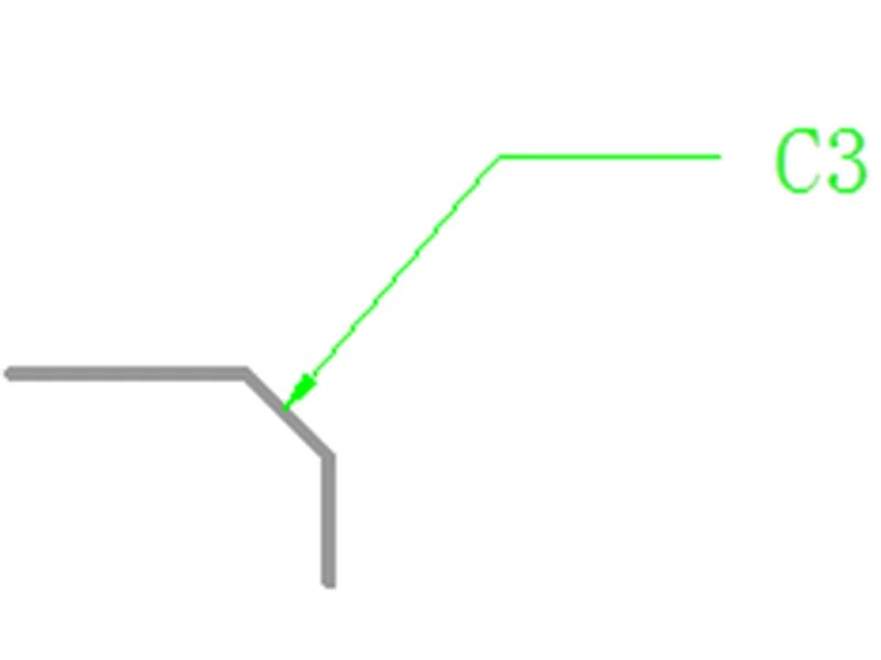
The meaning of this is: the bevel of the chamfer is 45 degrees, the length is 3mm, it should be noted that this length is not the length of the beveled edge. As shown in the figure below:

2. Direct drawing programming method.
As the name suggests, it is also programmed according to the dimensions marked on the drawing. Its format is as follows:
G01X _Z_R_ (arc)
G01X _Z_A_ (chamfer)
That is, in the G01 instruction directly after the addition of A or R .
Where: A is chamfering, R is rounding.
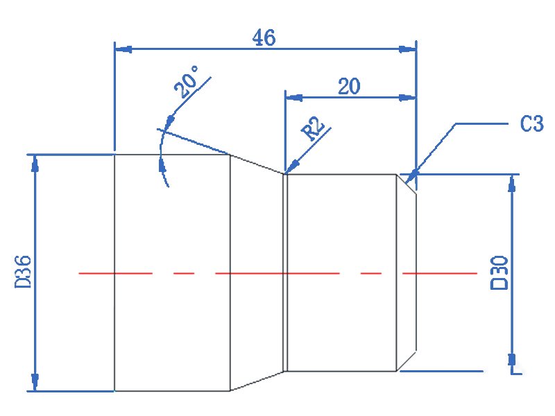
For example, the following sketch:
T0101
G97S1000M3
G0X24.Z2.
G1 Z0.F0.1
X30.A-45.
Z-20.R2.
X36.A-20.
Z-40.
G0X100Z2.
M01
The chamfer number after A is the angle between the chamfered edge and the Z-axis.
For example, the following sketch:

The angle between the chamfered edge and the Z-axis, if you look carefully at the picture above, the angle will appear as two values.
For example, the chamfer of C3: 135° with the positive direction of the Z-axis and 45° with the negative direction of the Z-axis.
For example, the chamfer of 20 degrees in the above figure: 160° with the positive direction of the Z-axis and 20° with the negative direction of the Z-axis
Well, the above programmed chamfer with the negative direction of the Z-axis is selected, so the A is followed by a negative.
Of course, you can also choose the angle with the positive direction of the Z-axis, then the following program is exactly the same as the above program:

Based on the above analysis, we look at the procedure in the following sketch:

NOTE:
When using direct drawing programming, some machines require a "comma" in front of A, or R.
For example: G01X24., A45.
For example: G01 X30.,A20.,R5.
Of course, you can find the system parameter #3405 and set the fourth digit CCR to 1, then there is no need to add a comma in front of the letter A and R.
